Welding mistakes often lead to structural failures that compromise the safety and longevity of heavy-duty fabrication. These errors agitate production timelines and increase costs through extensive rework or catastrophic field failures. By mastering the fundamental techniques outlined below, you can effectively eliminate welding defects and ensure every joint meets industrial-grade standards.
Why does poor prep cause welding defects?
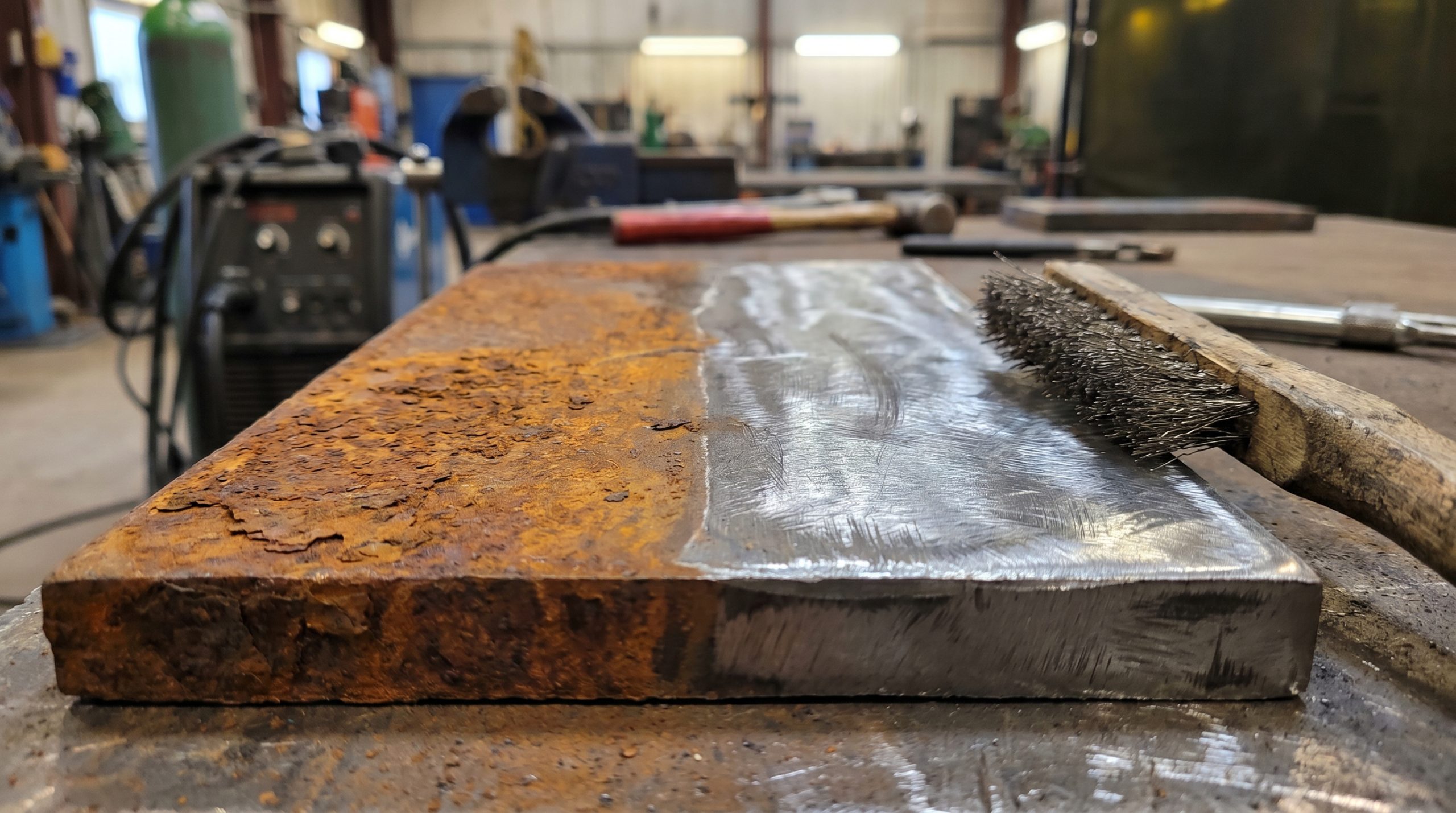
Poor preparation causes welding defects because surface contaminants like rust and oil vaporize under the arc, trapping gas within the cooling metal. This lack of cleanliness creates a barrier that prevents the filler material from fusing correctly with the base substrate.
Clean your metal surfaces
You must remove all oxidation, paint, and mill scale using a wire brush or grinder until the metal shines. Even microscopic layers of grease can ruin a high-pressure joint.
Use chemical solvents
Sometimes mechanical cleaning isn’t enough to remove deep oils or fingerprints. You should apply acetone to ensure a chemically pure surface before you strike your first arc.
- Remove rust and paint with a grinder.
- Wipe away oils using a clean rag and solvent.
- Sand down smooth surfaces to improve mechanical bonding.
How to inspect prep work?
Here is the kicker: if you can see any discoloration on the metal, it is not clean enough for a structural weld. You should always aim for a “bright metal” finish to guarantee maximum penetration.
Key Takeaway: Rigorous cleaning is the foundation of a strong weld and prevents 90% of contamination-related failures.
| Issue | Prevention Method | Required Tool |
|---|---|---|
| Surface Rust | Grinding/Wire Brushing | Angle Grinder |
| Oil/Grease | Solvent Wipe | Acetone & Lint-free cloth |
| Mill Scale | Heavy Sanding | Flap Disc |
Effective preparation ensures the molten pool remains pure throughout the transition from liquid to solid.
Can the wrong electrode lead to welding defects?
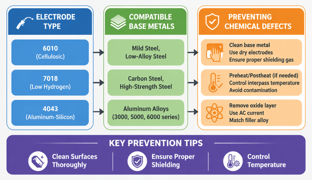
Using mismatched filler materials creates significant welding defects by introducing chemical incompatibilities that cause the joint to become brittle or crack under load. You must ensure that the mechanical properties of your electrode align perfectly with the metallurgy of your base plate.
Match alloy compositions
You should always check the manufacturer’s specifications to verify that your filler rod is rated for the specific steel or aluminum grade you are using. Mismatched chemistry leads to a weak molecular bond that will fail prematurely.
Select the right diameter
Using a rod that is too thick for thin material will lead to burn-through, while a thin rod on heavy plate fails to provide enough volume. You must select an electrode size that allows for a stable, controllable puddle.
- Verify electrode classification (e.g., 7018 vs. 6010).
- Check the material thickness against the rod diameter.
- Store low-hydrogen electrodes in a heated oven to prevent moisture.
Are you using dry rods?
But wait, there is more: moisture in an electrode coating will introduce hydrogen into the weld pool. This leads to hydrogen-induced cracking, a hidden failure that might not appear until the part is under stress.
Key Takeaway: Chemical compatibility and moisture control are non-negotiable for achieving structural integrity in heavy fabrication.
| Electrode Type | Base Metal | Main Advantage |
|---|---|---|
| 7018 (Low Hydrogen) | Carbon Steel | High strength, low crack risk |
| 6010 (Cellulosic) | Dirty/Rusty Steel | Deep penetration, fast freezing |
| 4043 (Al-Si) | Aluminum Alloys | Reduced cracking, smooth flow |
Selecting the right consumables is the first step in ensuring your project stands up to real-world forces.
How does bad technique create welding defects?
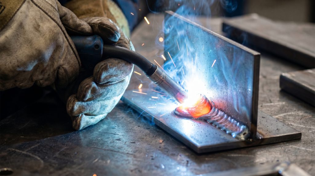
Bad technique creates welding defects by causing inconsistent heat distribution and improper shielding of the molten puddle. Even the most advanced equipment cannot compensate for a shaky hand or an incorrect torch angle that allows slag to get trapped inside the bead.
Control your travel speed
You must maintain a consistent speed to ensure the bead width and penetration remain uniform along the entire joint. Moving too fast results in a “cold” weld that sits on the surface without actually fusing.
Adjust your torch angle
Maintaining a 15-to-20-degree push or drag angle is essential for directing the shielding gas and heat correctly. If your angle is too steep, you risk losing gas coverage, which invites atmospheric contamination.
- Maintain a steady arc length.
- Keep your travel angle consistent.
- Watch the leading edge of the puddle for signs of fusion.
Is your arc length steady?
The truth is, even a slight variation in the distance between your tip and the workpiece can cause voltage fluctuations. You need to keep a tight, steady arc to prevent spatter and ensure deep, reliable penetration.
Key Takeaway: Manual precision and consistent movement are the only ways to achieve a professional-grade “stack of dimes” appearance.
| Technical Error | Visual Symptom | Corrective Action |
|---|---|---|
| Travel Too Fast | Thin, ropey bead | Slow down; watch the puddle fill |
| Steep Torch Angle | Porosity/Slag inclusion | Maintain 15-20 degree angle |
| Long Arcing | Excessive spatter | Tighten the gap to the workpiece |
Mastering your physical movements allows you to manipulate the molten metal with surgical precision.
Does heat mismanagement trigger welding defects?
Heat mismanagement triggers welding defects by either vaporizing the base metal through excessive amperage or failing to melt it sufficiently. You must calibrate your machine to the specific thickness of your material to find the perfect balance between penetration and structural warping.
Set the correct amperage
You should refer to a standardized welding chart before starting your project to ensure your settings are within the recommended range. High heat causes “undercut,” a groove at the edge of the weld that acts as a stress riser.
Monitor your voltage
In processes like MIG welding, your voltage settings control the arc’s stability and the fluidity of the puddle. You must adjust these settings based on the sound of the arc—it should sound like sizzling bacon, not a crackling fire.
- Test your settings on scrap material first.
- Adjust wire feed speed to match your voltage.
- Use a digital readout for repeatable accuracy.
Why is heat input critical?
Make no mistake: excessive heat will warp your workpiece, making it impossible to fit up with other components. You need to use intermittent welding techniques to distribute heat and prevent the metal from pulling out of shape.
Key Takeaway: Precise thermal control prevents both burn-through and lack of fusion, ensuring the metal remains structurally sound.
| Temperature Issue | Resulting Defect | Adjustment |
|---|---|---|
| Amperage Too High | Undercut / Burn-through | Lower the current/amps |
| Amperage Too Low | Lack of Fusion | Increase current/amps |
| High Heat Input | Metal Warping | Use tacks; weld in sections |
Balanced heat allows the liquid metal to flow smoothly and bond permanently without compromising the shape of the part.
Will skipping safety lead to welding defects?
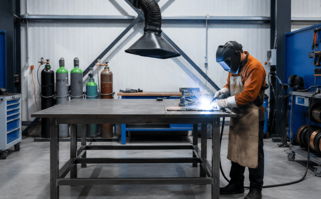
Skipping safety protocols indirectly causes welding defects by creating a distracting and hazardous environment that compromises your focus. When you are worried about fumes or burns, you cannot maintain the steady hand required for high-quality, high-stakes fabrication work.
Use proper ventilation
You must ensure your workspace has a fume extractor or adequate airflow to prevent toxic gases from obscuring your vision. If you can’t see the weld pool clearly, you will inevitably miss the joint or create an uneven bead.
Wear the right gear
High-quality auto-darkening helmets allow you to see exactly where you are striking the arc before the flash occurs. This prevents “stray arcs” on the surface of the metal, which are considered defects in many industrial codes.
- Wear flame-resistant gloves and jackets.
- Use a respirator in confined spaces.
- Clear the area of flammable debris.
Is your vision clear?
Here is the kicker: a scratched or dirty helmet lens can cause you to misjudge the puddle’s edge. You should replace your cover lenses frequently to ensure you have a sharp, high-contrast view of the molten metal.
Key Takeaway: A safe welder is a focused welder; protecting yourself ensures you have the clarity to execute flawless work.
| Safety Factor | Impact on Quality | Prevention |
|---|---|---|
| Poor Visibility | Missed joints / Wandering | Clean lens; better lighting |
| Fume Buildup | Distraction / Fatigue | Use fume extraction arms |
| Protective Gear | Consistency / Steady hand | High-dexterity welding gloves |
Maintaining a professional environment is the first step toward achieving a professional result in the workshop.
What cooling issues cause cracking welding defects?
Rapid cooling causes cracking welding defects because the metal shrinks too quickly, creating internal stresses that pull the joint apart. You must control the rate of thermal contraction, especially when working with thick sections of high-carbon or alloy steels.
Implement preheating
You should use a torch to warm thick base metals before you start welding to slow down the cooling process. This technique prevents “cold cracking” by allowing the hydrogen to escape and the crystals to form more gradually.
Avoid water quenching
You must never dip a freshly welded part into a bucket of water to cool it down for handling. This sudden temperature drop makes the metal extremely brittle and can cause immediate, visible cracks along the bead.
- Use a Tempilstick to check preheat levels.
- Wrap finished parts in a thermal blanket.
- Fill the crater at the end of each bead.
How to stop crater cracks?
But wait, there is more: the small pit at the end of a weld is the most common place for a crack to start. You should always pause and add a small amount of extra filler at the end of your run to fill the crater completely.
Key Takeaway: Controlled cooling is essential for maintaining the ductility and strength of the heat-affected zone.
| Cooling Method | Risk Level | Preferred Process |
|---|---|---|
| Water Quench | Critical Risk | Never use on structural welds |
| Air Cool | Moderate Risk | Best for thin, mild steels |
| Thermal Blanket | Low Risk | Best for heavy alloys and plate |
Managing the “cool down” phase is just as important as the welding phase for preventing structural failure.
Is poor gas flow causing porosity welding defects?
Poor gas flow causes porosity welding defects by allowing atmospheric nitrogen and oxygen to contaminate the molten pool. This results in a “Swiss cheese” appearance where the metal is riddled with tiny holes, significantly reducing its weight-bearing capacity.
Check your flow rate
You must set your regulator between 15 and 20 cubic feet per hour (CFH) for most indoor applications. If the flow is too low, you lose protection; if it is too high, turbulence can actually suck air into the arc.
Block the wind
Even a subtle breeze can blow your shielding gas away from the torch nozzle. You should always use welding screens or curtains when working outdoors or near open bay doors to maintain a stable gas envelope.
- Inspect gas hoses for leaks or kinks.
- Ensure the gas cylinder is not empty.
- Use the correct gas mixture (e.g., 75/25 Argon/CO2).
Is your nozzle clogged?
The truth is, spatter buildup inside your nozzle can redirect the gas flow away from the weld. You need to use nozzle dip or a dedicated cleaning tool to keep the path clear for the shielding gas.
Key Takeaway: Consistent gas coverage is the only barrier between your weld and the destructive gases in the atmosphere.
| Gas Flow Condition | Result | Solution |
|---|---|---|
| Too Low | Pervasive Porosity | Increase regulator setting |
| Too High | Turbulence/Contamination | Decrease regulator setting |
| Windy Environment | Shielding Loss | Use welding screens/tents |
Proper gas management ensures the chemical purity of the weld remains intact from start to finish.
How do fit-up errors result in welding defects?
Fit-up errors result in welding defects by creating massive gaps that are difficult to bridge with filler metal. You must spend the necessary time on alignment because a poor fit-up requires excessive heat and multiple passes, which increases the likelihood of distortion and internal stress.
Use precision clamps
You should utilize C-clamps and magnetic squares to hold your workpieces in the exact desired orientation. Once the parts are locked down, you can place small “tack welds” to ensure they don’t move during the final welding process.
Minimize the root gap
You must ensure that the edges of your joint are as close as possible to the design specifications. Large gaps lead to “slag traps” and lack of penetration, as the arc cannot effectively reach both sides of the joint.
- Measure twice to ensure perfect alignment.
- Use jigs for repetitive fabrication tasks.
- Degrease the clamping surfaces to avoid slippage.
Can you bridge the gap?
Here is the kicker: trying to “fill” a large gap with a single pass usually results in a weak, hollow bead. You need to use a “weave” technique or multiple stringer beads to build up the joint if the fit-up is imperfect.
Key Takeaway: Tight fit-up reduces the amount of filler needed and ensures a stronger, more efficient structural bond.
| Fit-up Issue | Structural Impact | Prevention |
|---|---|---|
| Large Gap | Poor penetration / Warping | Use precision cutting/jigs |
| Misalignment | Uneven load distribution | Use magnetic squares/clamps |
| No Tack Welds | Part movement / Twisting | Place tacks every few inches |
Perfect alignment on the bench leads to a perfect result on the finished product.
Can dirty equipment produce welding defects?
Dirty equipment produces welding defects by creating an unstable electrical circuit and erratic wire feeding. When your machine is neglected, the arc will stutter and pop, causing inconsistent penetration and leaving behind excessive spatter that you must later grind away.
Clean your ground clamp
You must ensure that your ground clamp is attached to clean, bare metal to maintain a solid electrical connection. A weak ground causes the machine to struggle, resulting in a “cold” arc that fails to melt the base metal properly.
Inspect the drive rolls
Dust and metal shavings can build up in the wire feed mechanism, causing the wire to slip or bind. You should blow out the liner with compressed air and check the tension on your drive rolls every time you change a spool.
- Replace contact tips regularly.
- Scrape spatter from the gas nozzle.
- Check cables for frays or loose connections.
Is your wire oxidized?
But wait, there is more: if your welding wire has sat in a humid shop for months, it may have developed a thin layer of rust. You should always store your wire in a dry environment to prevent it from carrying rust directly into the weld pool.
Key Takeaway: Preventive maintenance of your welding gear is just as important as the welding technique itself.
| Component | Maintenance Action | Frequency |
|---|---|---|
| Gas Nozzle | Scrape out spatter | Every few hours |
| Contact Tip | Replace if worn/ovaled | As needed/Monthly |
| Ground Clamp | Clean contact surfaces | Every project |
Reliable equipment is the silent partner in every high-quality weld you produce.
Do setting errors cause machine welding defects?
Setting errors cause machine welding defects because digital displays do not always reflect the actual electrical output at the torch. You must periodically verify your machine’s performance to ensure the voltage and amperage are accurate, especially when working on mission-critical structural components.
Verify your polarity
You must check that your machine is set to the correct polarity for the process you are using—DCEP for most MIG and Stick, and DCEN for TIG. Incorrect polarity causes an unstable arc, massive spatter, and a complete lack of penetration into the base metal.
Calibrate the machine
You should use a multimeter or a dedicated calibration service to ensure that “125 amps” on the screen actually means 125 amps at the electrode. Over time, internal components can drift, leading to welds that are consistently too cold or too hot.
- Double-check the wire feed speed (WFS).
- Match settings to the material gauge.
- Update firmware on digital machines.
Are your cables too long?
Make no mistake: using extremely long welding cables can cause a significant voltage drop. You need to compensate for this by slightly increasing the machine’s settings or moving the power source closer to the work area.
Key Takeaway: Verification of machine output ensures that your technique is backed by the precise energy levels required for fusion.
| Setting Error | Consequence | Verification Tool |
|---|---|---|
| Wrong Polarity | Massive spatter/Poor arc | Check machine terminals |
| Voltage Drop | Lack of penetration | Voltmeter at the torch |
| WFS Mismatch | Stubbing / Burn-back | Visual/Sound check |
Accurate settings provide the predictable foundation you need for repetitive, high-quality fabrication.
*
Summary of Excellence
By addressing these common errors, you transform your welding from a trial-and-error process into a precise science. At Brontec, our brand vision is to provide the highest-tier front-end protection through engineering excellence and flawless manufacturing. We have solved the problems of structural failure by adhering to these strict quality standards in every moose bumper and grille guard we produce. If you are looking for a partner who prioritizes durability and precision, contact us today to discuss your fleet’s protection needs.
*
Frequently Asked Questions
Can I weld over paint if I use high heat?
Absolutely not, as paint will vaporize and cause severe porosity within the weld bead. You must grind any coating back to bare metal to ensure the molten pool remains pure and the bond is structurally sound.
What’s the best way to prevent spatter on my nozzle?
The most effective method is using a ceramic-based anti-spatter spray or a nozzle dip before you begin. This creates a protective barrier that prevents molten droplets from sticking, allowing you to simply wipe the nozzle clean.
How do I know if my gas flow is too high?
You will know because the arc will become unstable and the finished weld will show signs of porosity despite the high flow rate. Excessive gas flow creates turbulence that pulls surrounding air into the shielding envelope, defeating the purpose of the gas.
Can I reuse an electrode that got wet?
It depends on the type, but for low-hydrogen rods like 7018, you must bake them in a rod oven at high temperatures to remove the moisture. If you use a wet rod without reconditioning, you risk hydrogen cracking and catastrophic joint failure.
How do I know if my weld has internal cracks?
You cannot always tell through visual inspection alone, which is why industrial projects use non-destructive testing like X-rays or ultrasonic checks. For shop-level verification, a dye penetrant test is a cost-effective way to reveal surface-reaching cracks that are invisible to the naked eye.